Basics of hardware hacking
This course shows the basics of hardware hacking using password auhenticaton code as an example.
Created by @maldr0id
Timing is key
The checkPass method takes longer to validate the password if some characters are correct. Take a look at step-by-step checkPass verification of two password guesses below – one with all characters incorrect and one with one correct character.
xxxxx |
pxxxx |
|---|---|
i = 0 |
i = 0 |
i < 5 |
i < 5 |
read PASSWORD[0] |
read PASSWORD[0] |
read buffer[0] |
read buffer[0] |
compare two values |
compare two values |
return false |
i = 1 |
| - | i < 5 |
| - | read PASSWORD[1] |
| - | read buffer[1] |
| - | compare two values |
| - | return false |
As you can see in the first case the checkPass for loop does only one iteration (since the first character is incorrect) and in the second case it does two (since the first character is correct, but the second one is incorrect). This is the whole purpose of returning from the method sooner - to make it run shorter and use less resources.
So can we detect this timing difference if we have access to the hardware? Let’s first set up our experiment.
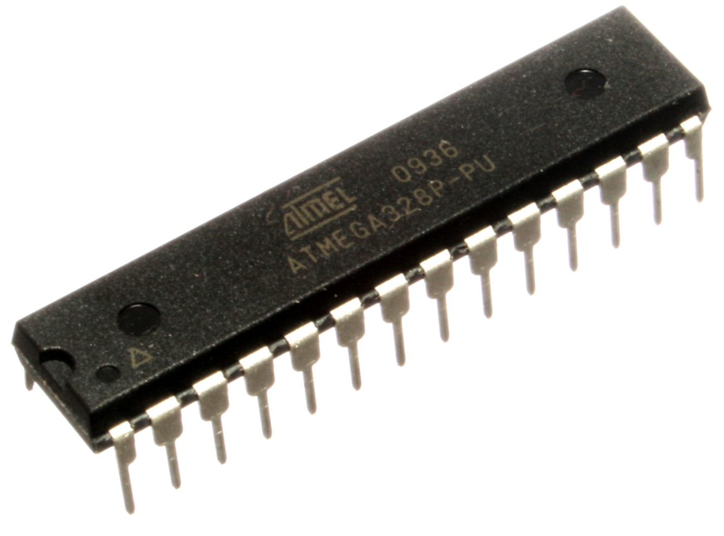
We will be using an Arduino Uno board, which uses an ATMega328 CPU, like the one pictured below.
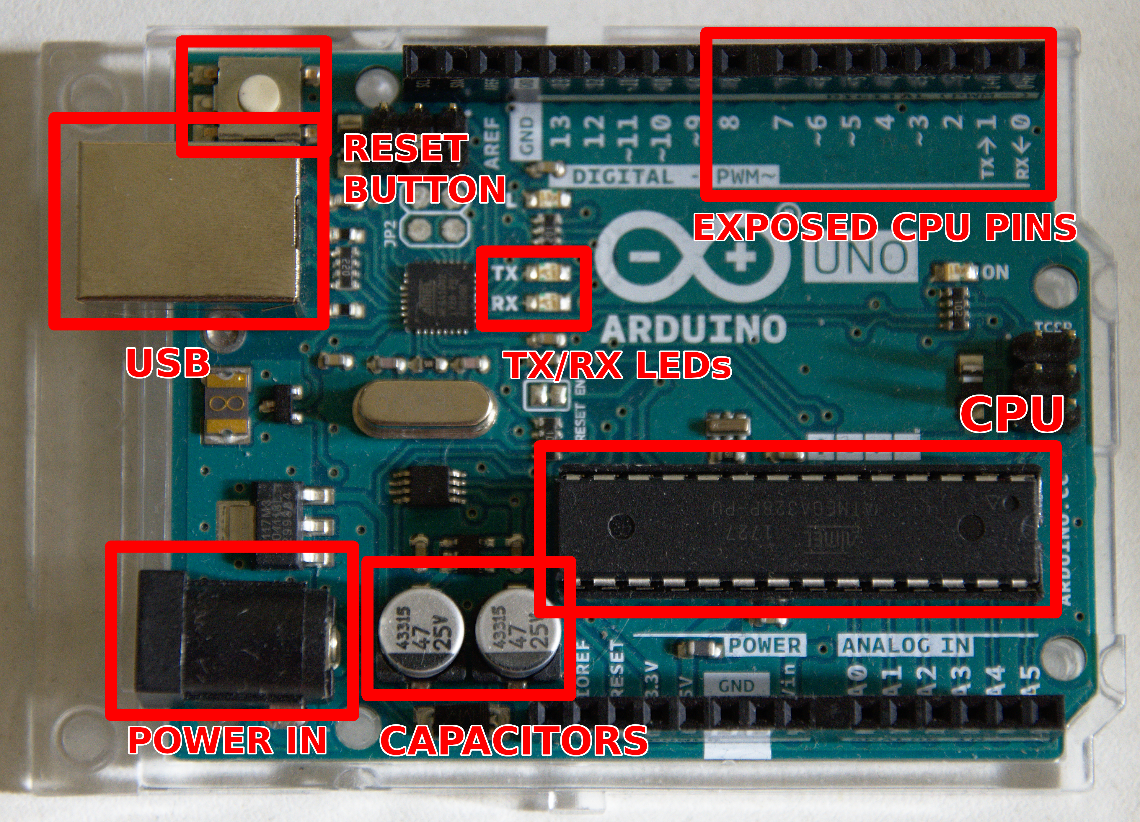
The board also has some additional elements responsible for making sure that the power flow is stable (capacitors), that we can communicate with a computer (the USB socket) that we can power the board using external power source and so on. Picture below shows the main components of the board.
The CPU can be programmed with our password checking routine using Arduino IDE. Once we paste the code we can compile it and upload it to the board. Then we just connect using a serial console to the board and we can see the password prompt, like the one below.
$ picocom /dev/ttyACM0 -b 115200
picocom v3.1

port is        : /dev/ttyACM0
flowcontrol    : none
baudrate is    : 115200
parity is      : none
databits are   : 8
stopbits are   : 1
...

Type [C-a] [C-h] to see available commands
Terminal ready
Password:
We now have access to the board with our code running on it. How will we measure the time it takes to validate the password? We can create a script which takes time measurements when we send out a password guess and when we receive the response, but there’s so much latency in that communication that the results will be useless.
Instead, we can use a logic analyser from Saleae. Logic analyser is a piece of hardware which can intercept and record the digital communication from the board. ATMega328 CPU uses serial communication, as does the USB (“S” stands for “serial”). It means that there are two wires – one to send the data (TX) and one to receive the data (RX). These are exposed through two pins of the ATMega328 CPU.
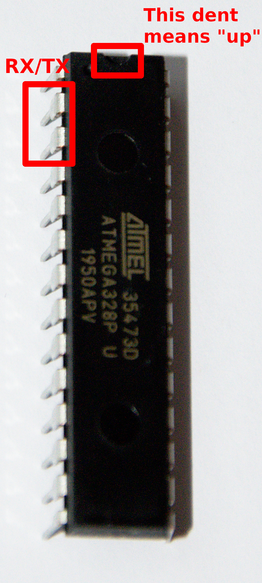
These pins are exposed on the board in the upper right corner (see the pictures of the board above). They are even convieniently labeled with “RX” and “TX”. This is the same data that is sent through USB to a serial terminal running on the computer. Let’s connect logic analyser to these two pins and record the whole communication.